
Pulse Leash Wiring Diagram
Feb 4, 2015 #1 wakebum2507 evltwns. Harness wiring kit for leash electronics stree/strip relay board.
Tran Brake Wiring Diagram Complete Wiring Schemas

I already purchased the nos solid state relay.

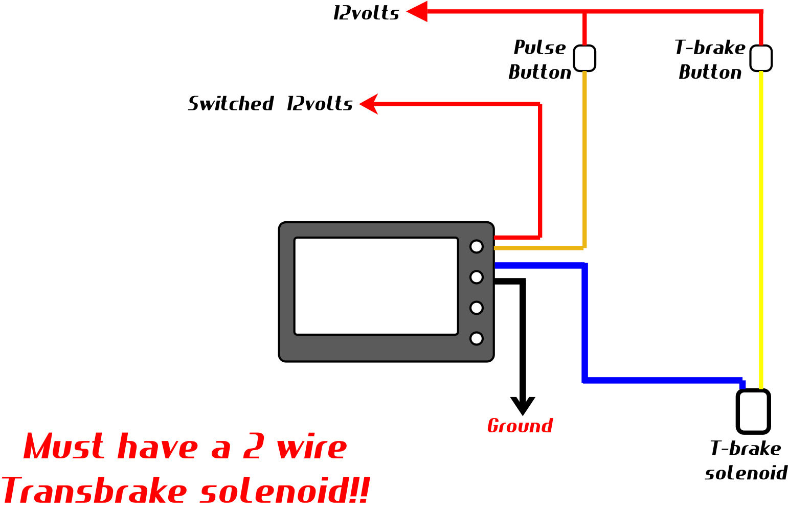
Pulse leash wiring diagram. Staging system designed to help with consistent staging of high powered turbocharged race cars. The white/red wire is the "input 2 control" wire. This unit is very accurate and consistant.
The white/red wire is the "input 2" wire. A slightly longer input pulse is needed to deactuate the relay: Pulse leash push button staging system.
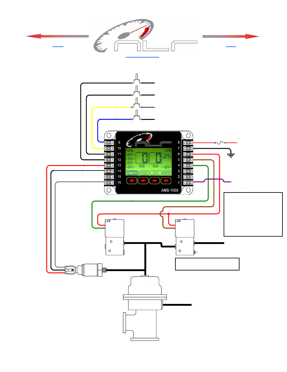
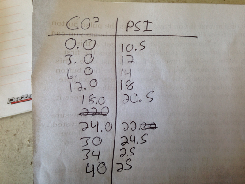
Now since it's a gate pressure controller you have to understand that the numbers you set in the controller are not boost. Every solenoid or relay in the car should have a suppression diode installed, some relays, or controllers, may have the diode built, other may not. Leash electronics pro 12 relay module.
It can be used to activate additional stages or disable a stage. This is the trigger wire used to activate stage 2. Joined may 12, 2013 messages 1,078 location oklahoma city.
Buy in monthly payments with affirm on orders over $50. Boost leash pulse leash combo unit leash electronics from isteam.wsimg.com dense walls in a building or home can reduce telephone signal strength. The next circuit wiring will be about the lighting impulse wiring diagram of the e ton axl50 an txl50.
Holley® has been the undisputed leader in fuel systems for over years. Wiring diagram, ground activation page 18 connecting to the analog output page 19 connecting a wideband controller to analog in page 19 warranty information warranty page 19 appendix a, pulse frequency detailed explanation page 20 appendix b, nitrous & fuel operation page 21 A vehicle wiring diagram is a lot like a road map, according to search auto parts.
No need to apply extreme, uncomfortable pressure on you brake peddle. Works with nearly any transbrake on the market including th400 th350 powerglide 4l80e 6r80e 727 c6 c4. Seems to have a ton of great features and im pretty excited to try it out.
Download full version pdf for leash boost controller instructions using the link below: Do any of you have experiance with this controller? Here are a number of highest rated pulse generator circuit diagram pictures on internet.
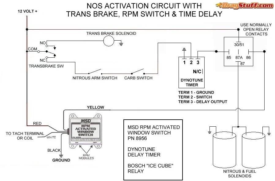
A digital timer is provided that can be used to activate an ignition retard controller or a 2nd stage of nitrous. Start date feb 4, 2015; Wiring board orders take around week to ship.
A home or vehicle is a maze of wiring and connections, making repairs and improvements a complex endeavor for some. Be sure to read about them first before making any wiring changes on your e ton vehicle this is for safety reason. It needs to be long enough for c1 to be discharged completely (or very nearly so) via r3.
We say yes this kind of pulse generator circuit diagram graphic could possibly be the most trending topic taking into account we ration it in google gain or facebook. Ati tci jake's coan proformance The boost leash is a 5 stage time based plus launch stage race/street style boost controller.
When the switch is released, or the input becomes high again, t1 stops conducting. Its submitted by government in the best field. Currently ive been using a knob style mbc.
I've tried to find a diagram, but i'm just getting more confused. Quick view compare choose options. Leash boost controller instructions ebook title :
If you are not sure which wire this is, consult a factory service manual. No more need for extra braking to prespool a car anymore. Simply changing a relay, could cost you weekends of failed racing.
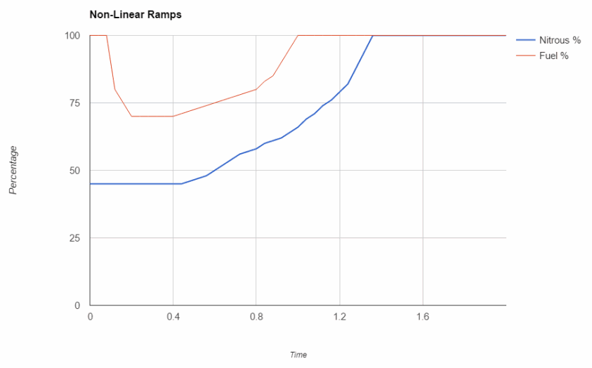
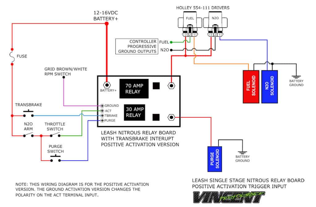
All, build is complete, all that is. Transients can be managed with the use of diodes across the coils, as well as proper wiring techniques. To operate in full progressive mode (i.e.
Impulse relays impulse relays are a form of latching relay that transfers the contacts with each pulse. $ $ $ boost leash boost controller (best seller) boost leash / pulse leash. View profile view forum posts view blog entries administrator.
Connect to either a switched 12v or ground microswitch output, or it can be connected to the signal output wire on a tps with either a rising or falling voltage. I recenlty purchased a boost leash/pulse leash boost/trans brake bump box controller used and i need the wiring diagram and instructions so that i can install it. Connect to either a 12v or ground microswitch input or it can be connected to the signal output wire on a tps with either a rising or falling voltage.
If this wire will not be used, heat shrink the end and secure it tightly out of. 12volt, ground, and launch input. Boost leash wiring for dummies thread starter wakebum2507;
Simultaneously, c1 is charged again, so that within a short time the base current of t2. The output from activation terminal is on (+12 volt applied). High hp turbo cars can enjoy smooth and consistent starts thanks to this box.
I'm looking for a wiring diagram that i can use with my terminator x.
New Leash Electronics Pro Street wiring board Facebook

Wiring and plumbing diagram, boost channel, Wastegate, Ssi
Tran Brake Wiring Diagram Complete Wiring Schemas

Boost Leash / Pulse Leash combo unit PRO Series Hartline
Leash Electronics added a new photo. Leash Electronics
Tran Brake Wiring Diagram Complete Wiring Schemas

New Leash Electronics N2O Leash nitrous progressive YouTube
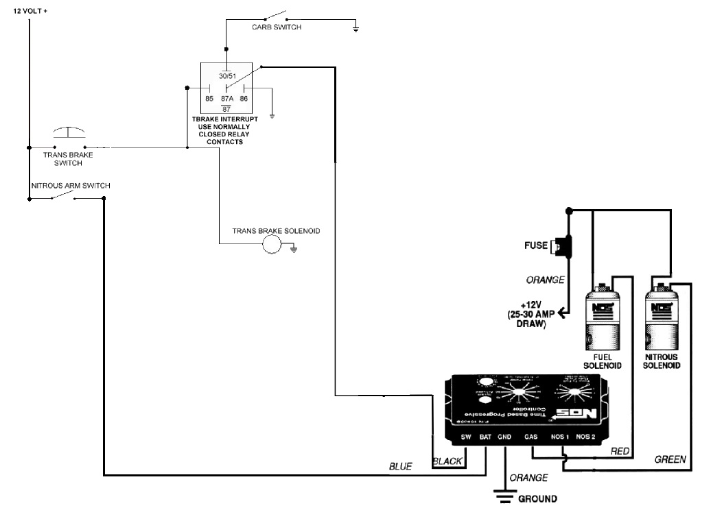
Transbrake Nitrous Wiring Diagram Wiring Diagram
How do Progressive Nitrous Controllers Work? Dragstuff
BOOST LEASH USERSadvise needed LS1TECH Camaro

Pulse Leash YouTube
New Leash Electronics Pro Street wiring board Facebook

Transbrake Nitrous Wiring Diagram Wiring Diagram

Covid19 Safety item, Oximeter , Oxygen Concentrator,UVC
Leash Electronics Home Facebook

Transbrake Nitrous Wiring Diagram Wiring Diagram
Boost Leash Boost Controller by Leash Electronics Full


boost leash YouTube

Boost Leash Demo YouTube
